


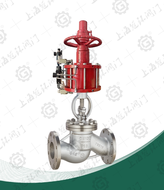
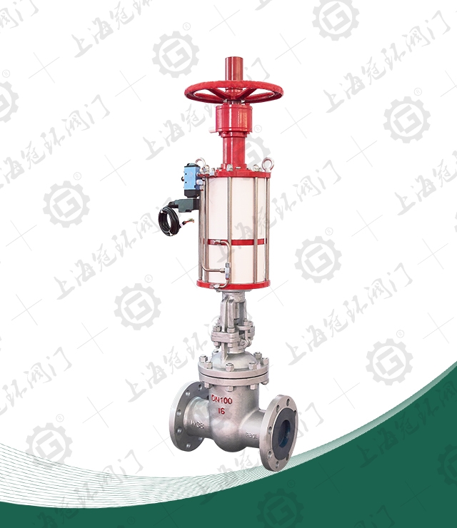
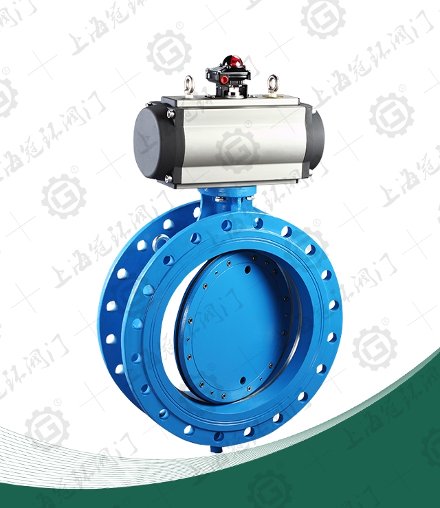
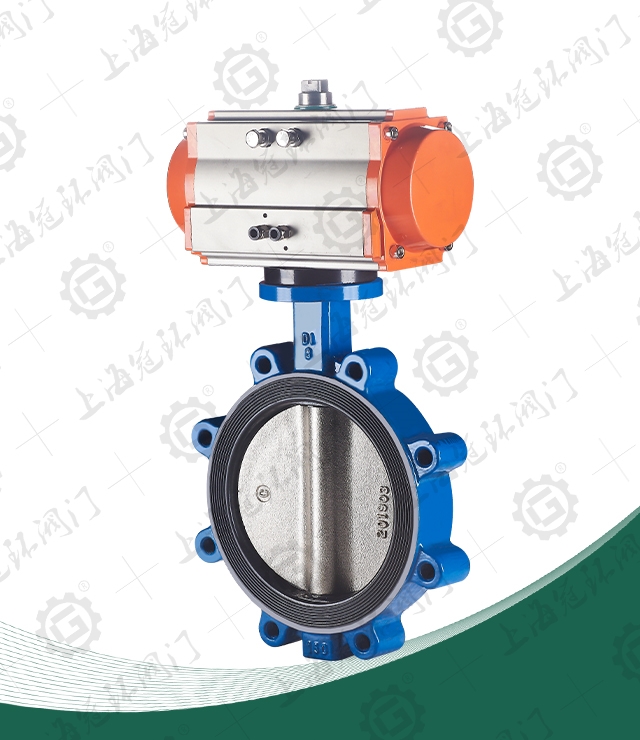
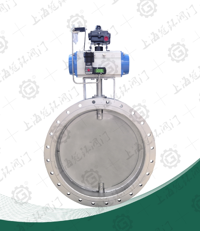
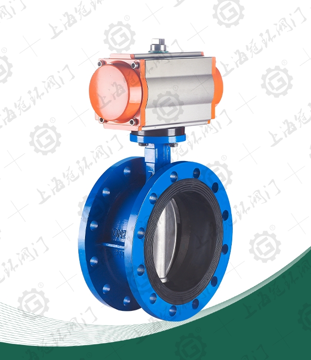
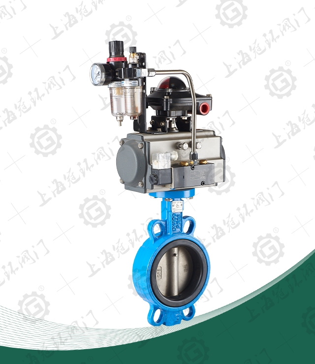
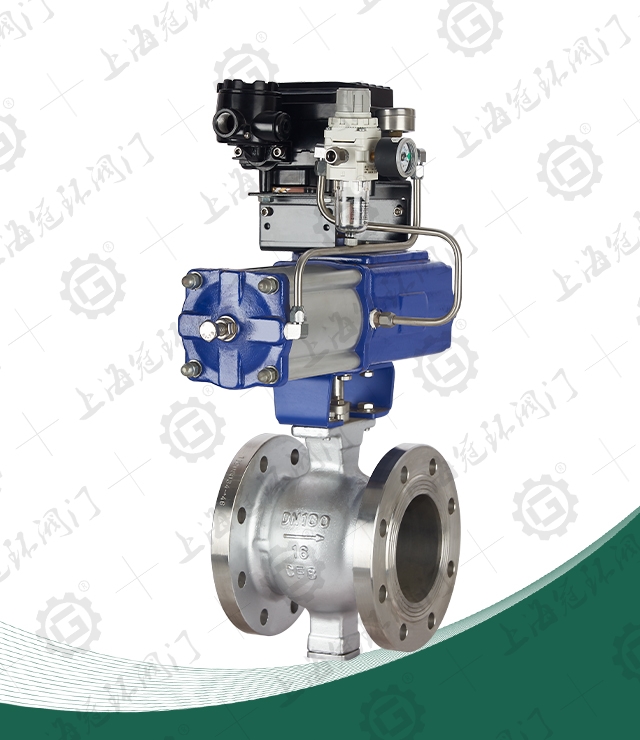
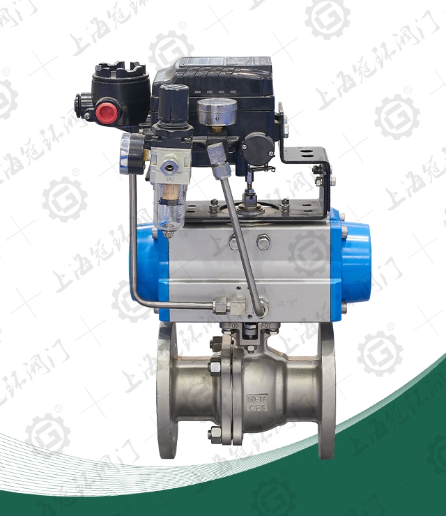
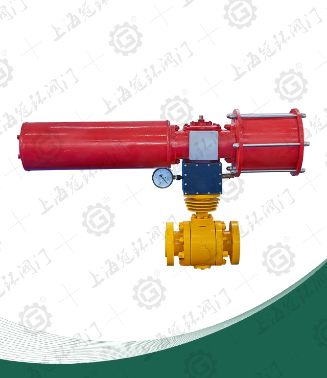
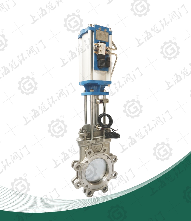
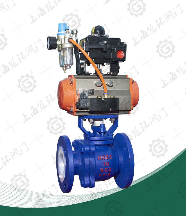
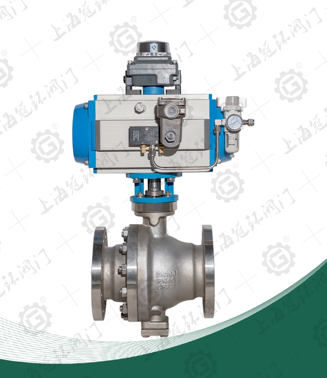
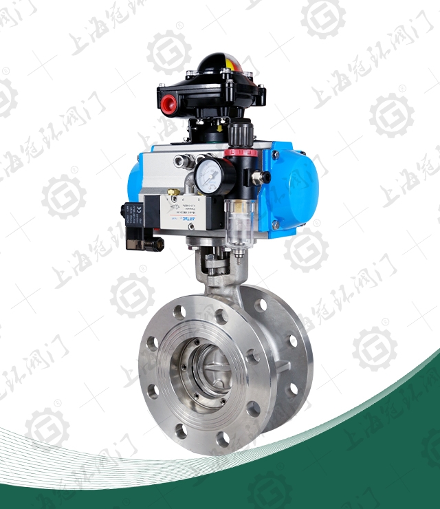
Pneumatic globe valve
Product model: J641H/Y/W
Nominal diameter: DN50~300mm
Nominal pressure: PN1.6~4.0MPa
Applicable temperature: -20℃-425℃
Applicable medium: water, oil, steam
Main material: carbon steel, stainless steel, etc.
Mode of action: double-acting, single-acting
Control mode: normally open, normally closed
Accessory selection: air source triplet, manual mechanism
 Contact us
The pneumatic flange globe valve adopts a double-acting cylinder, which uses the upper chamber air intake or the lower chamber air intake to remotely control the valve, which is convenient and flexible to operate. The structure is simple, the manufacture and maintenance are convenient; the working stroke is small, and the opening and closing time is short; the sealing surface of the closing body and the valve seat is sealed by a conical surface, which has small closing force, is resistant to erosion, and has reliable sealing. The valve seat can be a replaceable valve seat, which can be combined with the material of the sealing surface of the closing part in any combination to meet the requirements of working conditions and prolong the service life. The valve is a valve driven by compressed air. The compressed air enters the pneumatic actuator to drive the cylinder to connect the valve stem and the valve disc to make the lifting movement.
Product Features
1. Exquisite selection of materials, in line with relevant domestic and foreign standards, reasonable structure and beautiful appearance.
2. The valve disc and valve seat sealing surface are made of iron-based alloy surfacing or Stellite cobalt-based hard alloy surfacing, which has good wear resistance, high temperature resistance, corrosion resistance, scratch resistance and long service life. .
3. The valve stem is quenched and tempered and surface nitrided, which has good corrosion resistance and scratch resistance.
4. Various piping flange standards and flange sealing surface types can be used to meet various engineering needs and user requirements.
5. The valve body has a complete variety of materials, and the packing and gasket can be reasonably selected according to the actual working conditions or user requirements, and can be suitable for various pressure, temperature and medium working conditions.
6. The inverted seal is made of threaded connection seal seat or body surfacing austenitic stainless steel, which is reliable in sealing. The replacement of packing can be carried out without stopping the machine, which is convenient and quick, and does not affect the operation of the system.
Material of main parts
| NO | Part Name | Material | ||
| C | P4 | P6 | ||
| 1 | Body | WCB | ZG1Cr18Ni9Ti | 1Cr18Ni12Mo2Ti |
| 2 | Gasket | Flexible graphite + stainless steel | PTFE | PTFE |
| 3 | Bolt | 35 | 304 | 304 |
| 4 | Helical flap | WCB+ surfacing welding 304 or stelite, PTFE | ZG1Cr18Ni9Ti PTFE | ZG1Cr18Ni12Mo2Ti PTFE |
| 5 | Split collar | 1Cr18Ni9Ti | 1Cr18Ni9Ti | 1Cr18Ni12Mo2Ti |
| 6 | Disc cover | 1Cr18Ni9Ti | 1Cr18Ni9Ti | 1Cr18Ni12Mo2Ti |
| 7 | Stem | 2Cr13 | 1Cr18Ni9Ti | 1Cr18Ni12Mo2Ti |
| 8 | Nut | 35 | 304 | 304 |
| 9 | Eyebolt | 35 | 304 | 304 |
| 10 | Cap | WCB | ZG1Cr18Ni9Ti | ZG1Cr18Ni12Mo2Ti |
| 11 | Bolt | 35 | 304 | 304 |
| 12 | Gasket | 35 | 1Cr18Ni9Ti | 1Cr18Ni12Mo2Ti |
| 13 | Packing | Flexible graphite | PTFE | PTFE |
| 14 | Packing platen | WCB | ZG1Cr18Ni9Ti | ZG1Cr18Ni12Mo2Ti |
| 15 | Nut | 35 | 304 | 304 |

Main external connection dimensions PN1.6MPa
|
DN(mm) |
L |
D |
D1 |
D2 |
b |
f |
Z-φd |
H |
D0 |
|
15 |
130 |
95 |
65 |
45 |
14 |
2 |
4-14 |
291 |
120 |
|
20 |
150 |
105 |
75 |
55 |
14 |
2 |
4-14 |
300 |
140 |
|
25 |
160 |
115 |
85 |
65 |
14 |
2 |
4-14 |
353 |
160 |
|
32 |
180 |
135 |
100 |
78 |
15 |
2 |
4-18 |
390 |
180 |
|
40 |
200 |
145 |
110 |
85 |
16 |
2 |
4-18 |
518 |
200 |
|
50 |
230 |
160 |
125 |
100 |
16 |
3 |
4-18 |
555 |
240 |
|
65 |
290 |
180 |
145 |
120 |
18 |
3 |
4-18 |
630 |
280 |
|
80 |
310 |
195 |
160 |
135 |
20 |
3 |
8-18 |
683 |
280 |
|
100 |
350 |
215 |
180 |
155 |
20 |
3 |
8-18 |
745 |
320 |
|
125 |
400 |
245 |
210 |
185 |
22 |
3 |
8-18 |
855 |
360 |
|
150 |
480 |
280 |
240 |
210 |
24 |
3 |
8-23 |
870 |
400 |
|
200 |
600 |
335 |
295 |
205 |
26 |
3 |
12-23 |
954 |
400 |
|
250 |
650 |
405 |
355 |
320 |
30 |
3 |
12-23 |
1065 |
450 |
|
300 |
750 |
460 |
410 |
375 |
30 |
3 |
12-23 |
1185 |
500 |
Main external connection dimensions PN2.5MPa
|
DN(mm) |
L |
D |
D1 |
D2 |
b |
Z-φd |
f |
H |
D0 |
|
15 |
130 |
95 |
65 |
45 |
16 |
2 |
4-14 |
291 |
120 |
|
20 |
150 |
105 |
75 |
55 |
16 |
2 |
4-14 |
300 |
140 |
|
25 |
160 |
115 |
85 |
65 |
16 |
2 |
4-14 |
353 |
160 |
|
32 |
180 |
135 |
100 |
78 |
18 |
2 |
4-18 |
390 |
180 |
|
40 |
200 |
145 |
110 |
85 |
18 |
3 |
4-18 |
518 |
200 |
|
50 |
230 |
160 |
125 |
100 |
20 |
3 |
4-18 |
555 |
240 |
|
65 |
290 |
180 |
145 |
120 |
22 |
3 |
8-18 |
630 |
280 |
|
80 |
310 |
195 |
160 |
135 |
22 |
3 |
8-18 |
683 |
280 |
|
100 |
350 |
230 |
190 |
160 |
24 |
3 |
8-23 |
745 |
320 |
|
125 |
400 |
270 |
220 |
188 |
28 |
3 |
8-25 |
855 |
360 |
|
150 |
480 |
300 |
250 |
218 |
30 |
3 |
8-25 |
870 |
400 |
|
200 |
600 |
360 |
310 |
278 |
34 |
3 |
12-25 |
954 |
400 |
|
250 |
650 |
425 |
370 |
332 |
36 |
3 |
12-30 |
1065 |
450 |
|
300 |
750 |
485 |
430 |
390 |
40 |
4 |
12-30 |
1185 |
500 |


 +86-021-67895388
 shghfmc@163.com
  93862333