


 Contact us
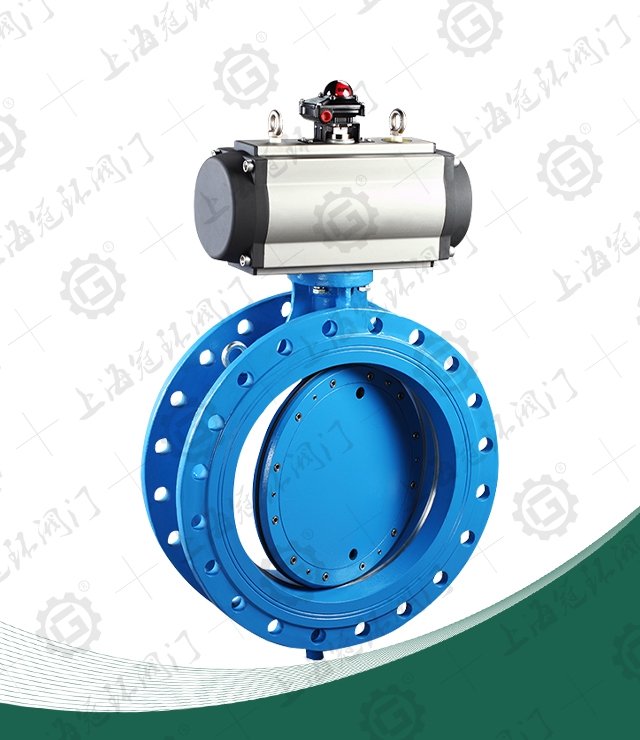
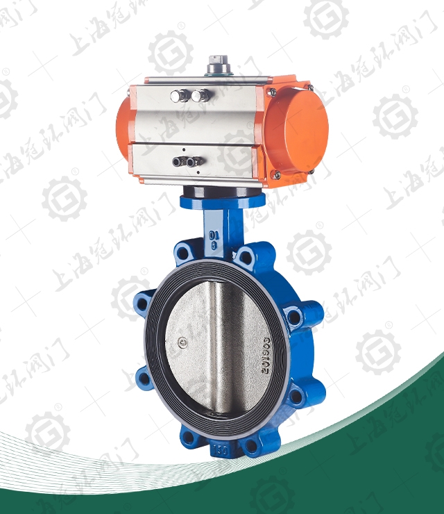
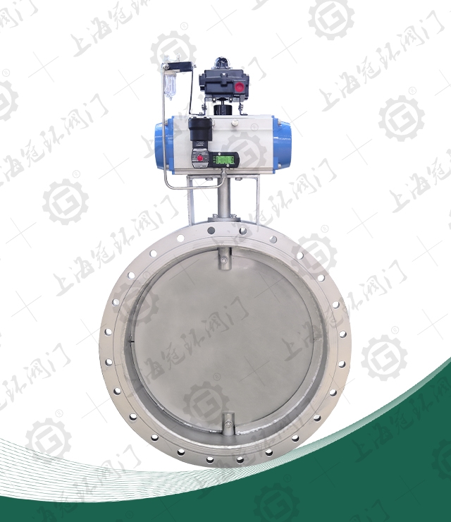
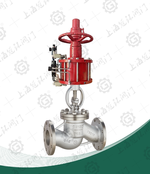
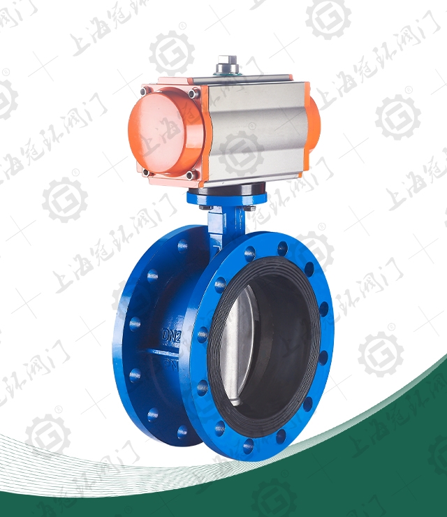
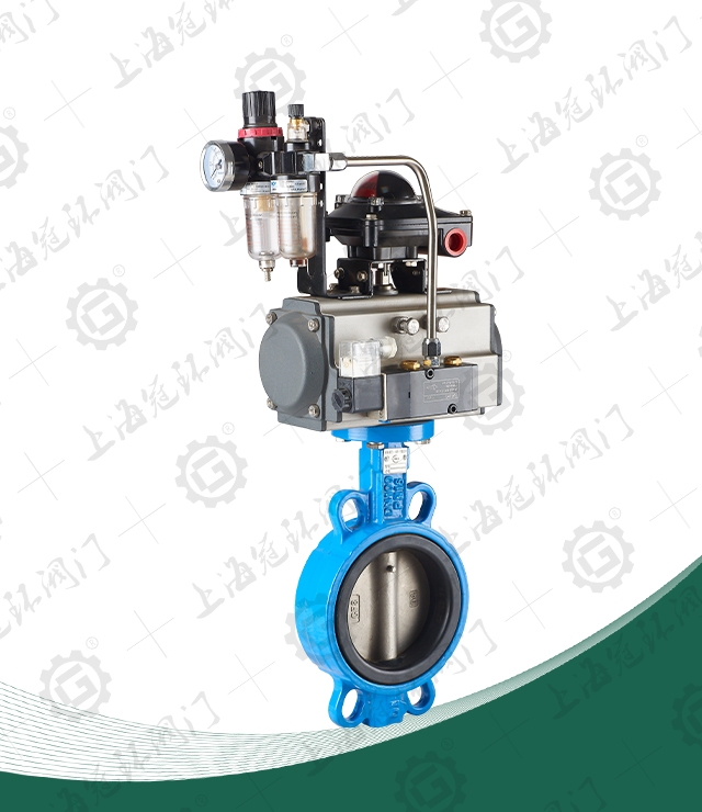
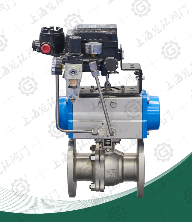
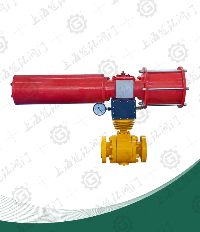
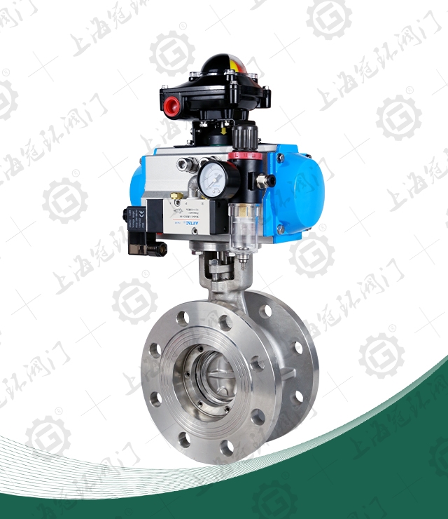
Product overview
Structural characteristics
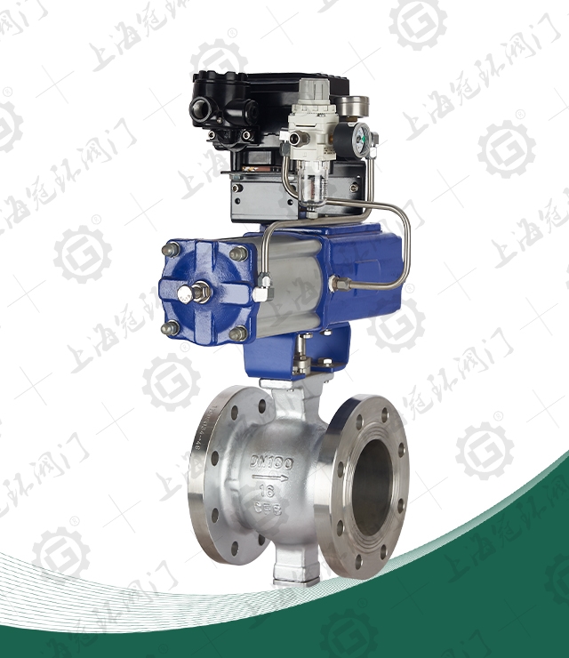
1, with excellent adjustment characteristics: pneumatic V-shaped ball valve has an approximate equal percentage of natural flow characteristics and up to 300:1 adjustable ratio. Pneumatic V-valves therefore provide precise control over a wide range of variations.
2, the opening and closing parts adopt V-shaped spherical structure, which solves the problem that the valve cavity is easy to deposit medium.
3, pneumatic V-shaped ball valve adopts double bearing structure, high mechanical stability, small starting torque, to ensure that the valve has a good sensitivity and induction speed.
4, high reliability (safety) : the valve body is a whole, durable, operation is not affected by pipeline pressure, and can avoid valve body leakage.
5, superior sealing of metal seat: Pneumatic V-shaped ball valve adopts movable metal seat, self-compensation function, and has superior sealing performance and long service life.
- Carried Standard
| design and manufacturing | GB12237-89、API608、API 6D、JPI 7S-48、BS5351、DIN3357 |
|
flange dimensions |
JB/T74~90、GB9112~9131、HGJ44~76、SH3406、ANSI B16.5、JIS B2212~2214、DIN2543 |
| structure length | GB12221-89、ANSI B16.10、JIS B2002、NF E29-305、DIN3202 |
| Inspection and test | JB/T 9092、API 598、GB/T13927 |
Material of main parts
|
DN15-DN300 | |||||
|
C | P | R | |||
|
valve body |
WCB | ZG1Cr18Ni9Ti | ZG1Cr18Ni 12Mo2Ti | ||
| sphere | 2Cr13 | 1Cr18Ni9Ti | 1Cr18Ni12MoTi | |||
| valve stem | 2Cr13 | 1Cr18Ni9Ti | 1Cr18Ni12MoTi | |||
|
seal ring |
Enhanced polytetrafluoroethylene, para polystyrene | |||||
| padding | Polytetrafluoroethylene, flexible graphite | |||||
| Applicable condition |
applicable medium |
Steam, water, oil |
|
|||
|
applicable temperature |
-29℃~425℃ | |||||
Main connection size
|
25 | 32 | 40 | 50 | 65 | 80 | 100 | 125 | 150 | 200 | 250 | 300 |
| L | 102 | 102 | 114 | 124 | 143 | 165 | 194 | 213 | 229 | 243 | 297 | 338 |
| L1 | 62 | 62 | 62 | 75 | 80 | 100 | 115 | 130 | 160 | 200 | 240 | 334 |
| H | 60 | 60 | 65 | 95 | 105 | 120 | 140 | 155 | 165 | 205 | 240 | 270 |
| H1 | 277 | 285 | 305 | 364 | 379 | 389 | 402 | 426 | 453 | 473 | 540 | 590 |
| A | 140 | 140 | 140 | 164 | 164 | 190 | 210 | 247 | 276 | 348 | 378 | 524 |
|
PN1.6MPa flange dimensions |
||||||||||||
| D | 115 | 140 | 150 | 165 | 185 | 200 | 220 | 250 | 285 | 340 | 405 | 460 |
| D1 | 85 | 100 | 110 | 125 | 145 | 160 | 180 | 210 | 240 | 295 | 355 | 410 |
| D2 | 65 | 76 | 84 | 99 | 118 | 132 | 156 | 184 | 211 | 266 | 319 | 370 |
| n-φd | 4-14 | 4-18 | 4-18 | 4-18 | 4-18 | 8-18 | 8-18 | 8-18 | 8-22 | 12-22 | 12-26 | 12-26 |
|
PN2.5MPa flange dimensions |
||||||||||||
| D | 115 | 140 | 150 | 165 | 185 | 200 | 235 | 270 | 300 | 360 | 425 | 485 |
| D1 | 85 | 100 | 110 | 125 | 145 | 160 | 190 | 220 | 250 | 310 | 370 | 430 |
| D2 | 65 | 76 | 84 | 99 | 118 | 132 | 156 | 184 | 211 | 274 | 330 | 389 |
| n-φd | 4-14 | 4-18 | 4-18 | 4-18 | 8-18 | 8-18 | 8-22 | 8-26 | 8-26 | 12-26 | 12-30 | 16-30 |


 +86-021-67895388
 shghfmc@163.com
  93862333