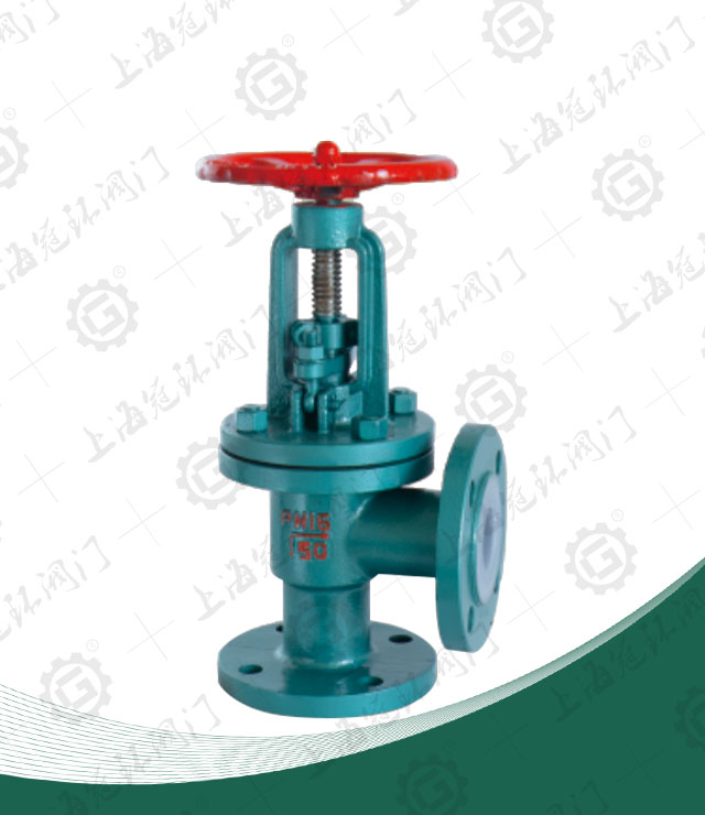
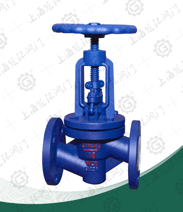
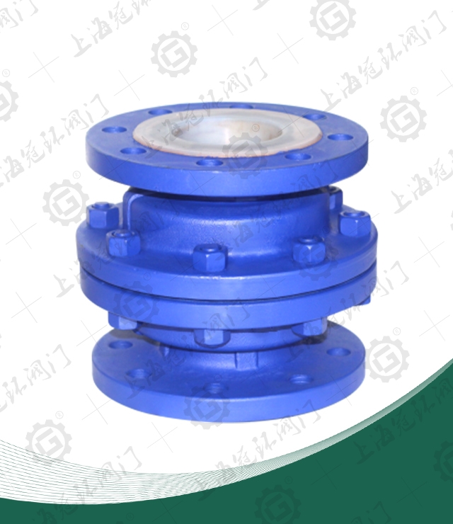
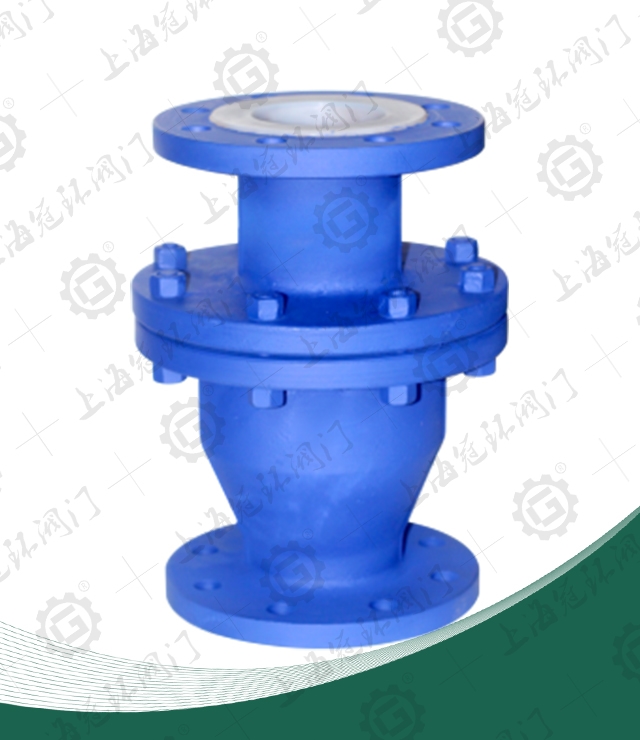
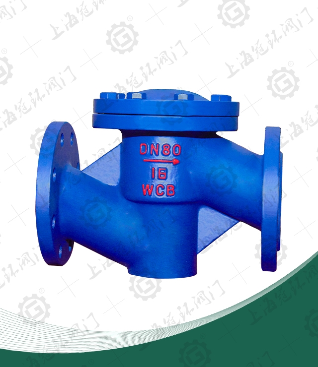
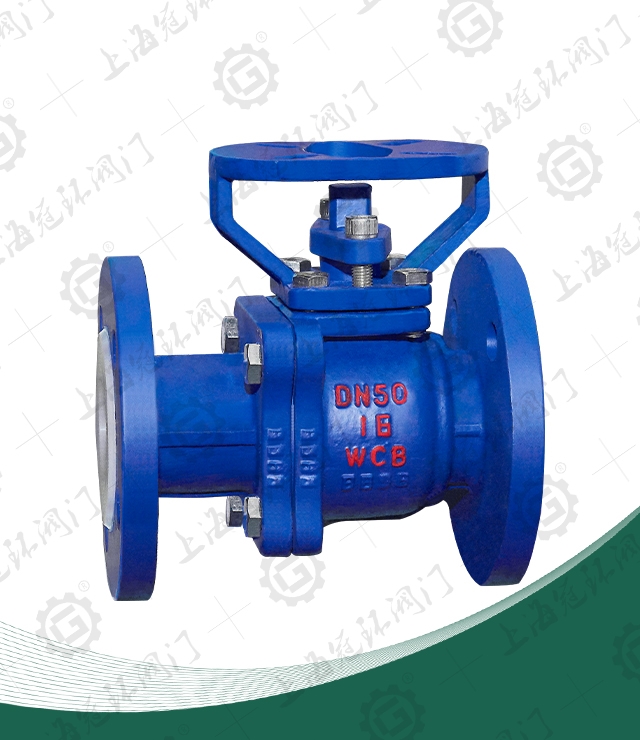
Fluorine Lined Angle Globe Valve
Nominal diameter: DN50-300mm
Service pressure: 1.6Mpa - 6.4Mpa
Connection mode: flange connection
Operation mode: manual
Function: switch function
Use medium: water. Oil.Steam. Corrosion resistant media
Main material: cast steel.Stainless steel. Chromium-molybdenum steel
Manufacturing standard: mechanical department standard or custom non - standard
Product Description
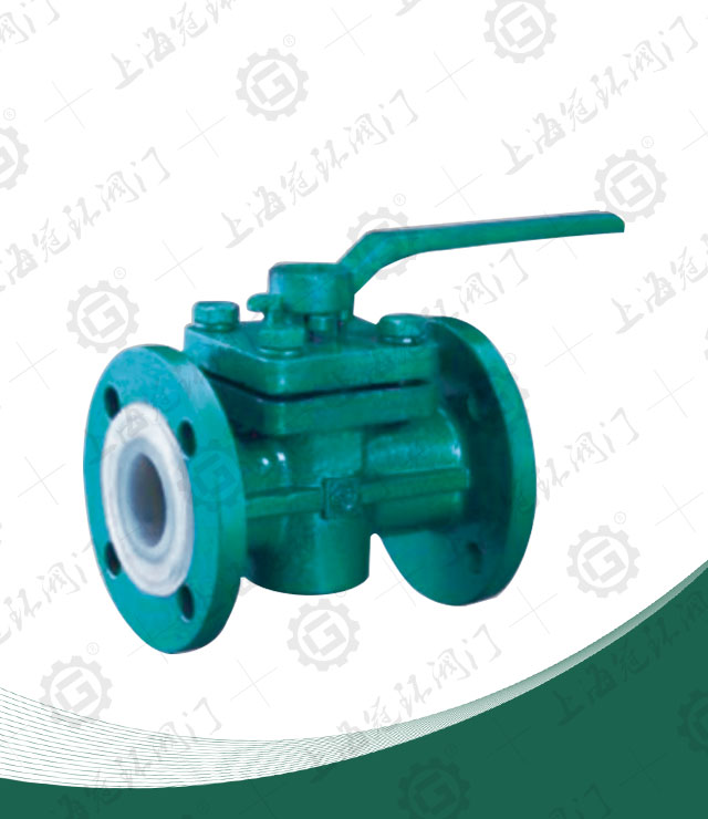
J44F46 Fluorine Lined Angle Globe Valve produced and sold by Baigang valve group by the valve stem and the central axis along the valve to do the lifting movements of the valve, the pipeline is mainly used to connect or cut off the medium in the pipeline, but can not do with the throttle.
Basic structural features
1, plastic lining J41 straight through, J45 straight slip, J44 angle valve, with a compact structure, opening and closing flexible, corrosion resistance, short stroke (generally nominal pass through 1/4) and so on. Is widely used in petroleum, chemical and other piping systems to do truncated media, but the plastic lining of the globe valve is strictly prohibited for flow control, so as to avoid throttling at high-speed media flow erosion damage sealing surface.
2, the valve flap and stem design as a whole structure, to prevent the pipeline due to pressure fluctuations caused by the possibility of internal parts out of the body, compact structure, the use of safety.
Main components of the material table| Serial number | Part Name | grey cast iron | Cast steel | Stainless steel acid-proof | Ultra-low carbon stainless steel acid-proof | ||
| Z | C | P | R | PL | RL | ||
| 1 | Body / bonnet | HT250 | WCB | CF8 | CF8M | CF3 | CF3M |
| 2 | Sphere / stem | 25 | 2Cr13 | 1Cr18Ni9 | 1Cr18Ni12Mo2Ti | 00Cr18Ni10 | 00Cr17Ni14Mo2 |
| 3 | Lining / seat | PCTEF (F3), FEP (F46), PFA (Soluble F4), PP, PO | |||||
| 4 | Packing gland | WCB | CF8 | CF8M | CF3 | CF3M | |
| 5 | filler | PTFE (F4) | PTFE (F4) | PTFE (F4) | |||
| 6 | Easter bolt | 35 | 1Cr17Ni2 | 1Cr17Ni2 | |||
| 7 | Stem nut | ZCuAl10Fe3 | ZCuAl10Fe3 | ZCuAl10Fe3 | |||
| 8 | Tighten the bolts | 35 | 1Cr17Ni2 | 1Cr18Ni9Ti | |||
| 9 | Nut | 45 | 0Cr18Ni9 | 0Cr18Ni9 | |||
| 10 | handle | WCB | WCB | WCB | |||
Main shape and connection dimensions
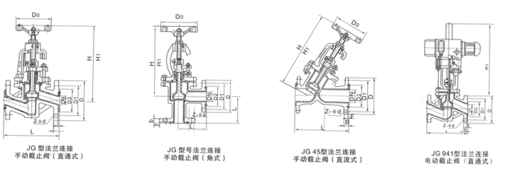
| Nominal diameter | L | D | D1 | D2 | f | b | Z-φd | |
| DN (mm) | NPS (inch) | PN1.0MPa | ||||||
| 15 | 1/2 | 90 | 95 | 65 | 45 | 2 | 14 | 4-φ14 |
| 20 | 3/4 | 95 | 105 | 75 | 55 | 2 | 16 | 4-φ14 |
| 25 | 1 | 100 | 115 | 85 | 65 | 2 | 16 | 4-φ14 |
| 32 | 11/4 | 105 | 135 | 100 | 78 | 2 | 18 | 4-φ18 |
| 40 | 11/2 | 115 | 145 | 110 | 85 | 3 | 18 | 4-φ18 |
| 50 | 2 | 125 | 160 | 125 | 100 | 3 | 20 | 4-φ18 |
| 65 | 21/2 | 145 | 180 | 145 | 120 | 3 | 20 | 4-φ18 |
| 80 | 3 | 155 | 195 | 160 | 135 | 3 | 22 | 4-φ18 |
| 100 | 4 | 175 | 215 | 180 | 155 | 3 | 22 | 8-φ18 |
| 125 | 5 | 200 | 245 | 210 | 185 | 3 | 24 | 8-φ18 |
| 150 | 6 | 225 | 280 | 240 | 210 | 3 | 24 | 8-φ23 |
| 200 | 8 | 275 | 335 | 295 | 265 | 3 | 26 | 8-φ23 |
| 250 | 10 | 325 | 390 | 350 | 320 | 3 | 28 | 12-φ23 |
| 300 | 12 | 375 | 440 | 400 | 368 | 4 | 28 | 12-φ23 |
| PN1.6MPa | ||||||||
| 15 | 1/2 | 90 | 95 | 65 | 45 | 2 | 14 | 4-φ14 |
| 20 | 3/4 | 95 | 105 | 75 | 55 | 2 | 16 | 4-φ14 |
| 25 | 1 | 100 | 115 | 85 | 65 | 2 | 16 | 4-φ14 |
| 32 | 11/4 | 105 | 135 | 100 | 78 | 2 | 18 | 4-φ18 |
| 40 | 11/2 | 115 | 145 | 110 | 85 | 3 | 18 | 4-φ18 |
| 50 | 2 | 125 | 160 | 125 | 100 | 3 | 20 | 4-φ18 |
| 65 | 21/2 | 145 | 180 | 145 | 120 | 3 | 20 | 4-φ18 |
| 80 | 3 | 155 | 195 | 160 | 135 | 3 | 22 | 8-φ18 |
| 100 | 4 | 175 | 215 | 180 | 155 | 3 | 24 | 8-φ18 |
| 125 | 5 | 200 | 245 | 210 | 185 | 3 | 26 | 8-φ18 |
| 150 | 6 | 225 | 280 | 240 | 210 | 3 | 28 | 8-φ23 |
| 200 | 8 | 275 | 335 | 295 | 265 | 3 | 30 | 8-φ23 |
| PN2.5MPa | ||||||||
| 15 | 1/2 | 90 | 95 | 65 | 45 | 2 | 16 | 4-φ14 |
| 20 | 3/4 | 95 | 105 | 75 | 55 | 2 | 16 | 4-φ14 |
| 25 | 1 | 100 | 115 | 85 | 65 | 2 | 16 | 4-φ14 |
| 32 | 11/4 | 105 | 135 | 100 | 78 | 2 | 18 | 4-φ18 |
| 40 | 11/2 | 115 | 145 | 110 | 85 | 3 | 18 | 4-φ18 |
| 50 | 2 | 125 | 160 | 125 | 100 | 3 | 20 | 4-φ18 |


 Contact us





 +86-021-67895388
 shghfmc@163.com
  93862333